
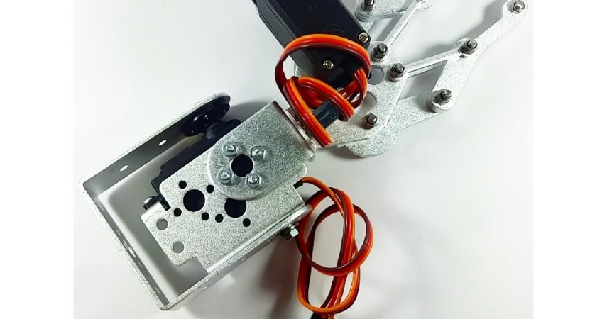
Robotic Arm 2 Degrees of Freedom Assembly Guide
The Robotic Arm 2 Degrees of Freedom is a robotic arm kit that offers a manipulator claw and bracket made in aluminum. It has two degrees of freedom, one is for controlling the arm, the other the rotation of the arm. The kit is also easy to construct, and could be done by yourself.
HARDWARE SPECIFICATIONS
- Full aluminum alloy
- Supports 2 degrees of freedom
- Maximum clamp opening – 54 mm
PARTS LIST
For this assembly guide, we will need the following materials:
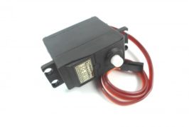
- SG5010 Servo Motor – https://www.bitstoc.com/product/250/
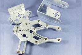
- Robotic Arm Kit
ASSEMBLY
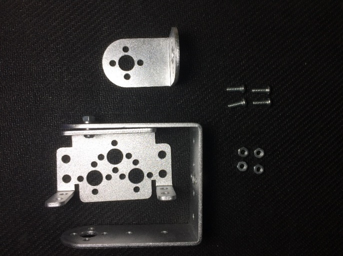
Prepare the following parts below. These parts are for the base of the robotic arm that will house one servo motor for rotating the arm.
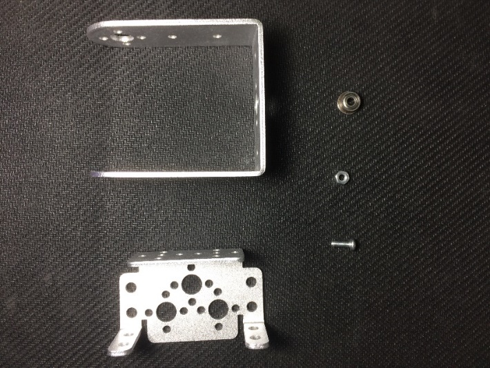
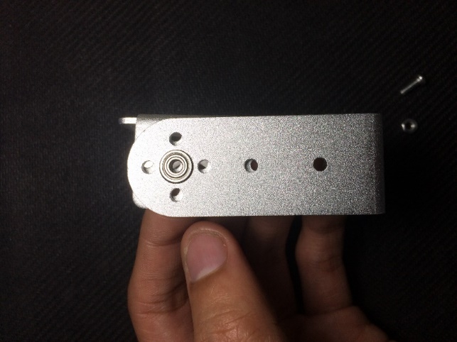
Orient the parts as shown below. The servo holder is inside the base platform of the servo motor.
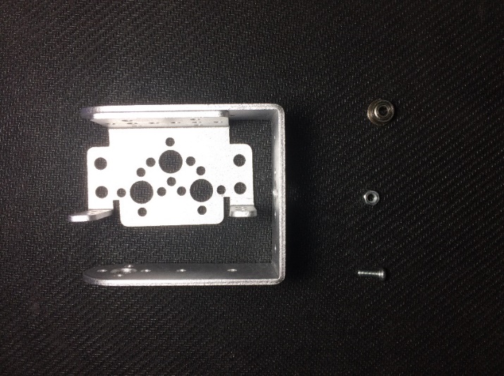
Align the top holes patterned like a “t” of the servo motor holder to the base’s equivalent “t” pattern. Place the bearing between the two aluminum pieces, in the center hole of the “t” pattern. Place the larger base of the bearing in front of the servo holder, while the smaller base facing the base holder.
Secure the bearing with screw and nut.
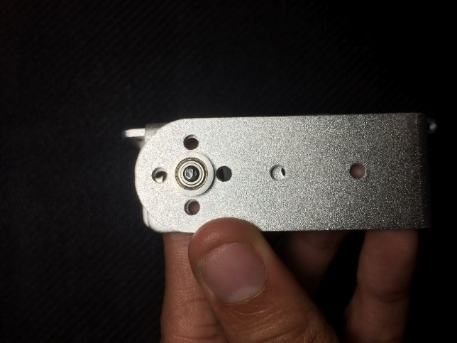
Try rotating the servo holder. The nut should be as steady and non-moving as possible.
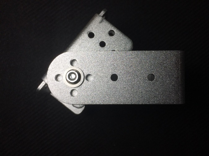
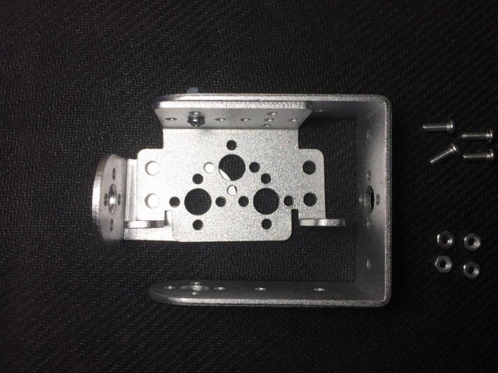
Prepare the parts below: The assembled servo holder and base, L-shaped aluminum, and four pairs of screw and nut.
Mount the L-shaped aluminum to the back of the servo holder. Align the “t” pattern holes to the top of the servo holder. Fasten them using screw and nut, with the cap inside the servo holder.
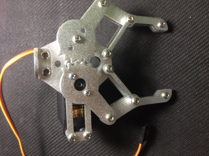
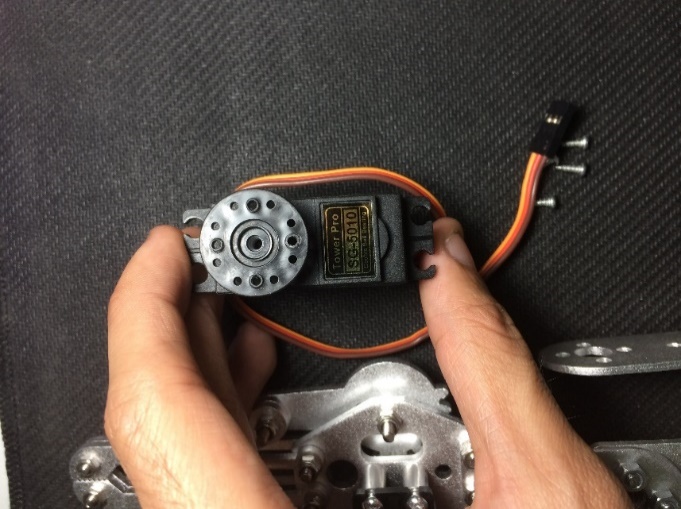
Prepare the robotic arm, servo motor and 4 screws.
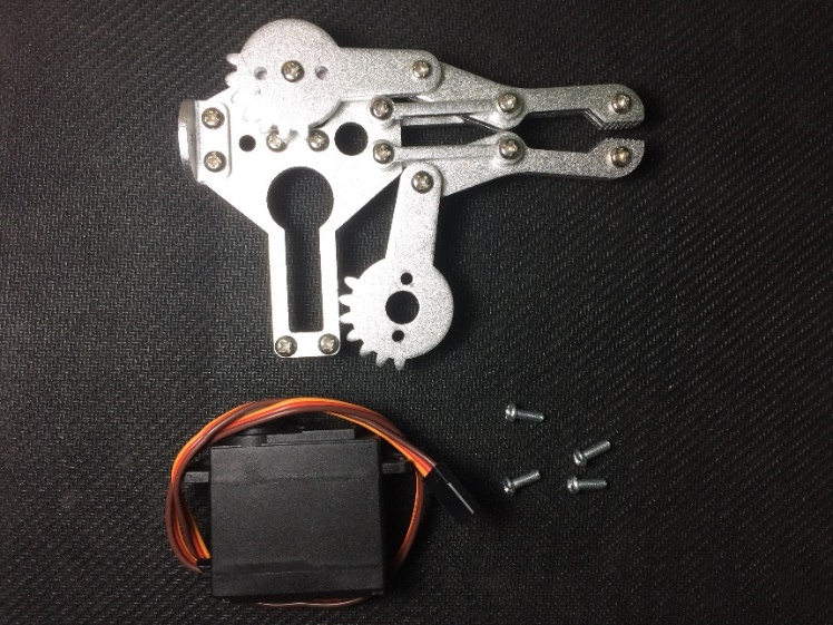
Mount the servo motor into the robotic arm, in the manner shown below. There are 4 screw holders in the robotic arm, which double serve as a mounting and guide for you to place the servo motor.
Secure the servo motor into the robotic arm using the screws.
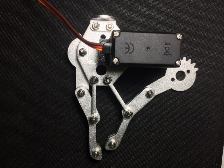
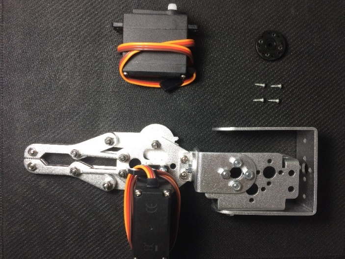
Prepare the arm, circular jig of the servo motor, as well as a regular screw (black) and wood screw (grey). The wood screw is a pointed screw provided in the servo motor product.
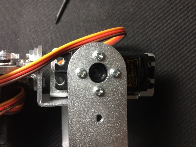
Place the circular jig into the shaft of the servo motor. Secure the jig using the standard screw into the servo motor.
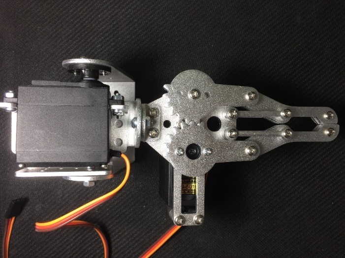
Align the part of the robotic arm to be connected to the servo motor into the servo motor. Ensure that the teeth of the robotic arm are aligned.
Secure the robotic arm into the servo motor using the two wood screws.
Prepare the assembled robotic arm, base, and two pairs of screw and nut.
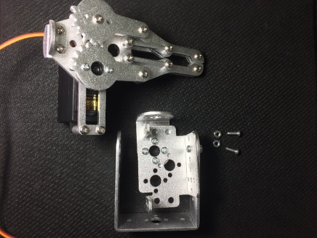
Place the robotic arm on top of the L-shaped bar, with the holes of the robotic arm and the bar aligned. Secure the arm into the bar using screw and nut.
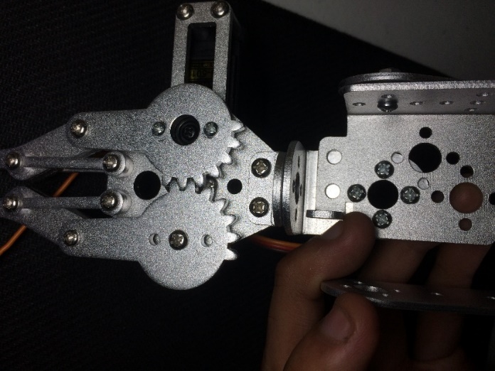
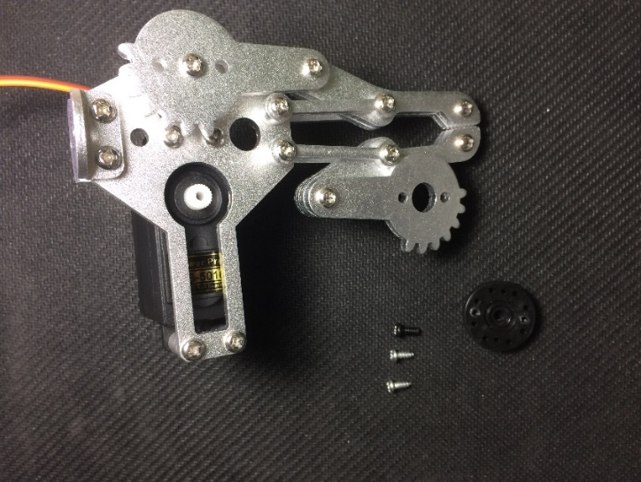
Prepare the robotic arm, servo motor, circular jig, four wood screws.
Mount the circular jig into the servo motor.
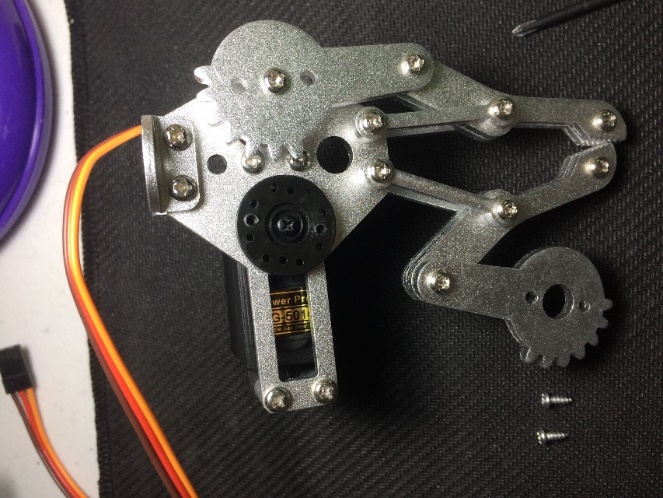
Slide the servo motor into the servo holder, with the holes of the circular jig aligned into the base of the servo motor.
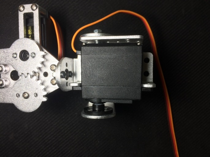
Secure the circular jig into the base using the four wood screws.
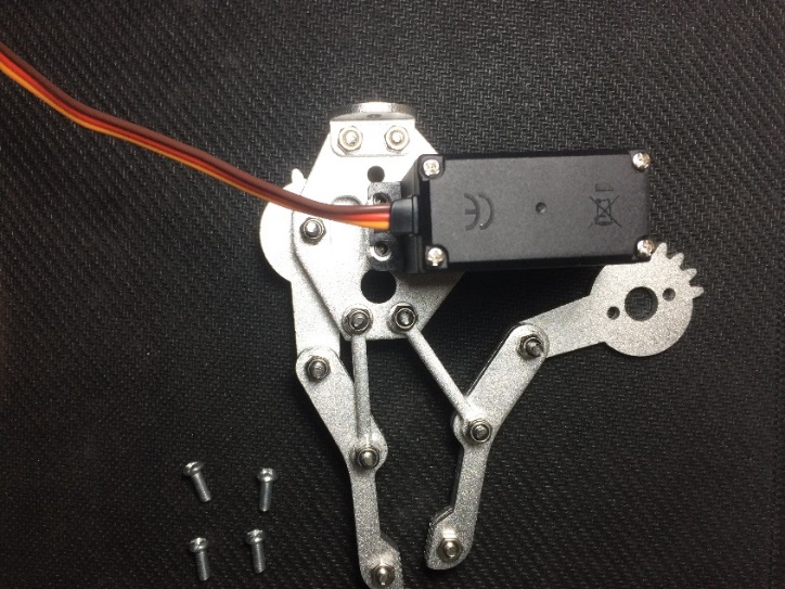
Prepare the robotic arm and four pairs of screw and nut.
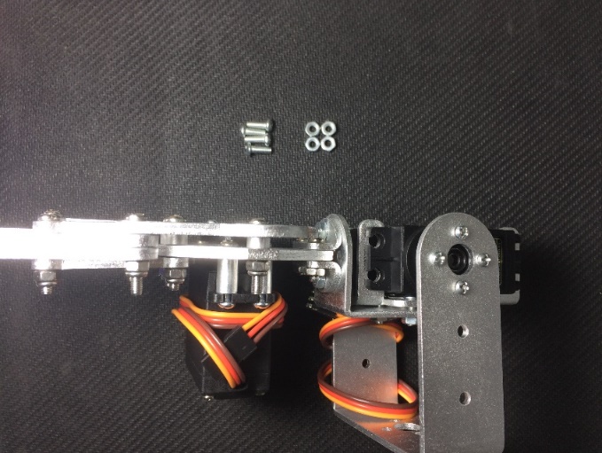
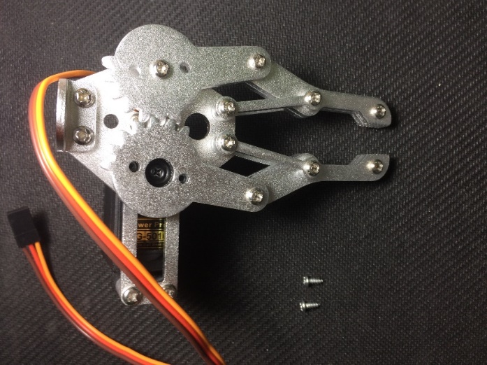
Secure the servo motor into the servo holder using the screw and nut.
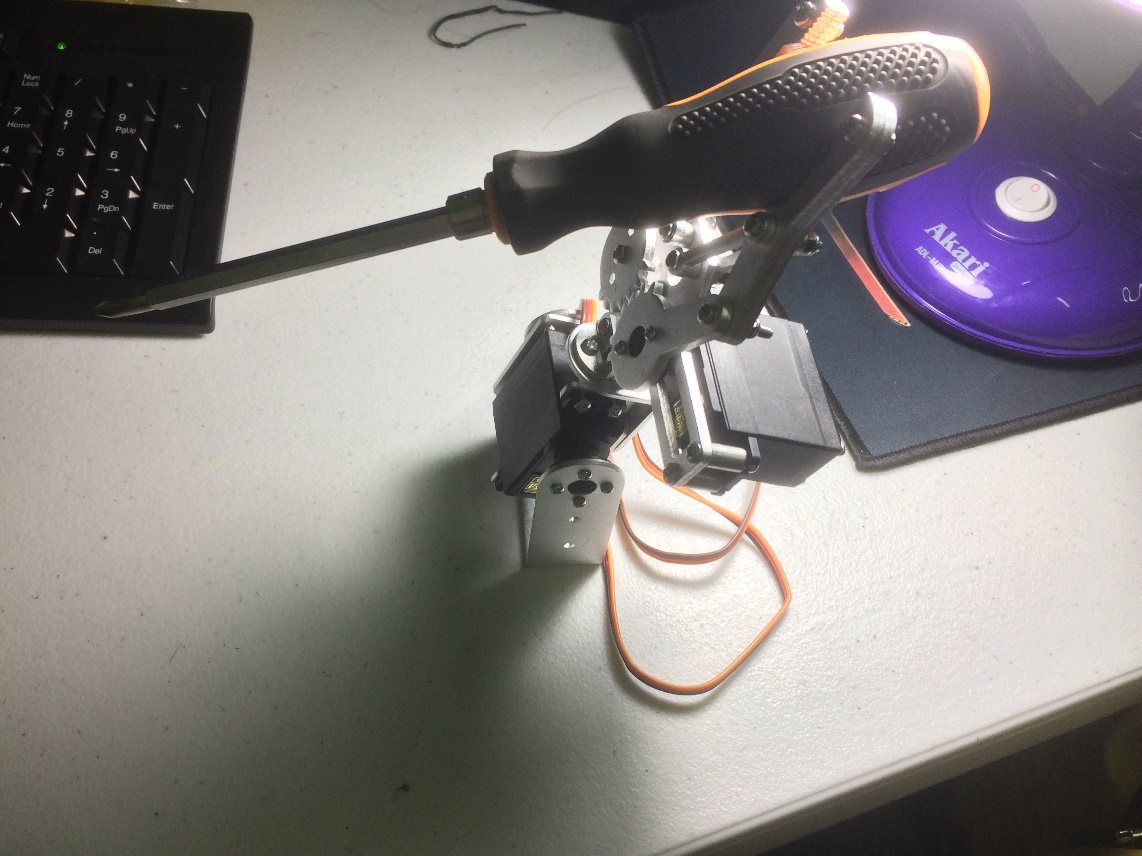
Your Robotic Arm is now complete!
EXAMPLE PROJECT
Click on this guide for the example code and setup: Robotic Arm Kit Example Guide