
1 Channel 5V Relay Module Quickstart Guide
Get a PDF version of this file here!
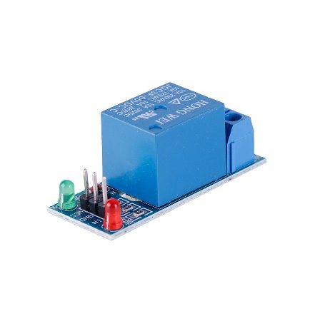
The 1 Channel 5V Relay Module is a great module for controlling your system that have voltages greater than the capacity of microcontrollers such as Arduino and Raspberry. Use this relay for controlling basic components, such as motors for your self-made systems. This can also be used for controlling equipment using AC voltages such as lamps, chargers, televisions, etc.
HARDWARE SPECIFICATIONS
- Control systems of up to 250V, 10 A for AC equipment or 30V, 10A for DC equipment
- Can be controlled by common microcontrollers such as Arduino Uno, Raspberry Pi and ESP8266.
- Built-in red and green LEDs for operation indication.
PARTS LIST
For this quickstart guide, we will need the following materials:
- 1 – green LED
- 1 – red LED
- 1 – Arduino Uno
- 2 – 330Ω resistor
- Connecting wires
- 1 – breadboard
- 1 channel relay module

1 Channel 5V Relay Module
₱109.00
Add to cartQuick View

Arduino UNO R3 with USB Cable
₱695.00
Add to cartQuick View
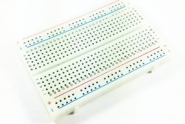
Breadboard – Half Size, 400 points
₱99.00
Add to cartQuick View

Connecting Wires – Male-Female 40pcs, 20cm
₱149.00
Add to cartQuick View

LED – Green (5mm)
₱4.00
Add to cartQuick View

LED – Red (5mm)
₱4.00
Add to cartQuick View

Resistors – 330 ohms (Through Hole, 1/4W ; 4pcs/pack )
₱2.00
Add to cartQuick View
HARDWARE OVERVIEW
The 1 channel relay have 3 pins to be connected to the microcontroller: VCC, GND and IN. For the system to be controlled, the pins NO, COM and NC are used.
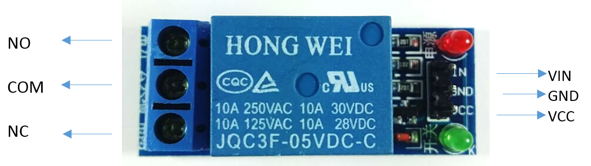
The table below describes the function of each pin in the module
| INPUT | Description | |
| VIN | Controls the state of the relay. This is connected to a digital pin in Arduino Uno or GPIO in Raspberry Pi. | |
| GND | To be connected to the GND pin in a microcontroller. | |
| VCC | Supplies power to the module. Could be connected to a +5V pin or +3.3V pin. | |
| OUTPUT | ||
| NO | Normally Open pin in a relay. When relay is in off state, this pin stays open with respect to COM pin. When relay is in on state, this pin connects with COM pin. | |
| COM | Common pin. Connected to one part of the system to be controlled. | |
| NC | Normally Closed pin in a relay. When relay is in off state, this pin stays close with respect to COM pin. When relay is in on state, this pin disconnects with COM pin. | |
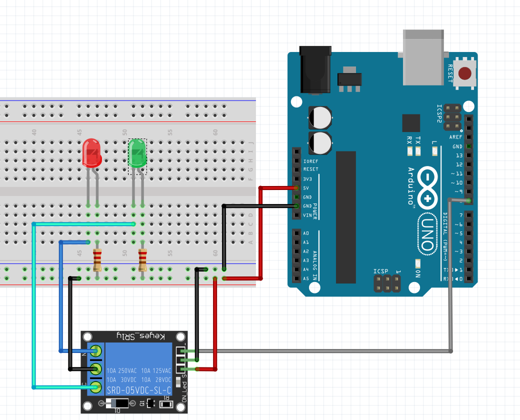
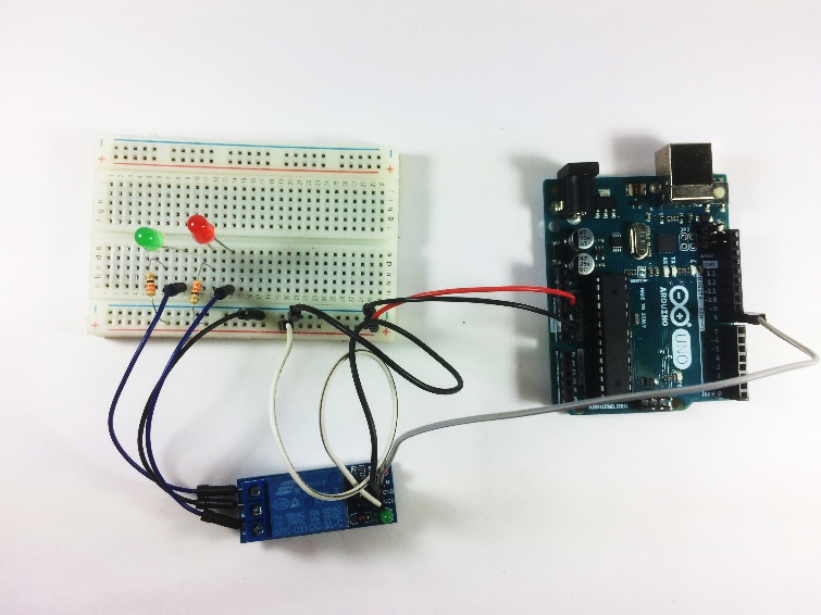
WIRING CONNECTION
Setup the circuit as shown below:
ARDUINO CODE
Open Arduino IDE. Set the board to Arduino/Genuino Uno. Copy the code below to the programmer:
int relay=8;

void setup() {
// put your setup code here, to run once:
pinMode(relay, OUTPUT);
}

void loop() {
// put your main code here, to run repeatedly:
digitalWrite(relay, HIGH);
delay(2000);
digitalWrite(relay, LOW);
delay(2000);
}
Upload the code. The LEDs should blink alternately every two seconds.
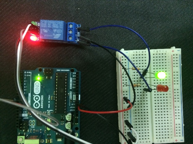
OUTPUT
If the relay is in its off state, the built-in green LED in the module is in off state. The green LED in the breadboard becomes bright while the red LED remains off.
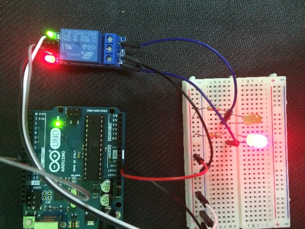
If the relay is in its on state, the built-in green LED in the module switches on. The green LED in the breadboard switches off while the red LED switches on.
APPLICATIONS
You can find more uses of the relay in the sample projects below:
Home Automation Using Raspberry Pi 2 and Windows 10 IoT by CC BY-NC