
Color Sensor Module TCS3200 Quickstart Guide
Get the PDF version of this guide here!
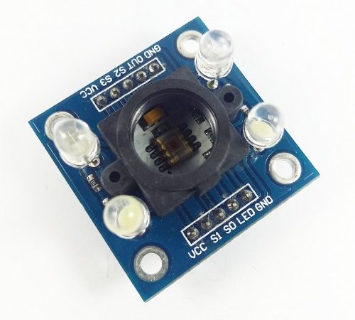
The Color Sensor Detector Module detects various colors. It detects different values of red, blue and green to detect colors through its sensor board. With easy-to-connect pins, you can directly interface it into your desired microcontroller, such as Arduino Boards.
HARDWARE SPECIFICATIONS
- High-Resolution Conversion of Light Intensity to Frequency
- Single-Supply Operation (2.7 V to 5.5 V)
- 8×8 array of photodiodes (16 with green filters, 16 with red filters, 16 with blue filters, 16 with no filter)
PARTS LIST
For this quickstart guide, we will need the following materials:
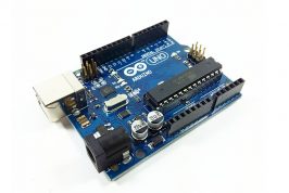
- 1 – Arduino Uno
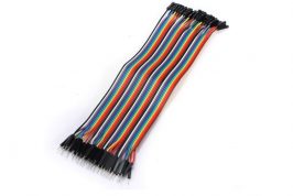
- Connecting wires
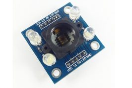
- 1 – Color Sensor Module TCS3200
HARDWARE OVERVIEW
For this guide, we will be using the following pins: VCC, GND, S0, S1, S2, S3 and OUT.
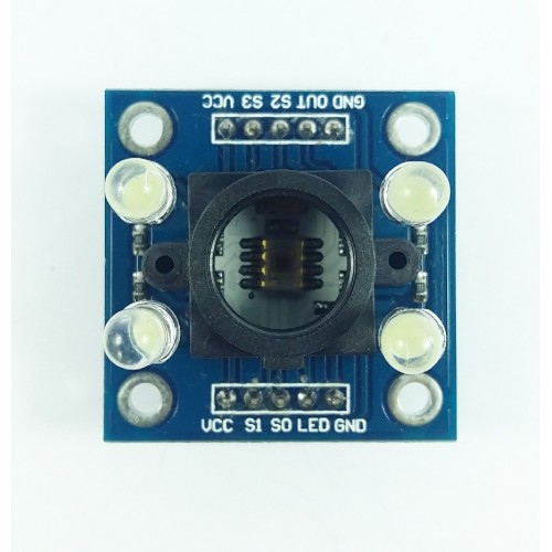
The table below describes the function of each pin in the module
| INPUT | Description | |
| GND | To be connected to the GND pin in a microcontroller. | |
| VCC | Supplies power to the module. Connected to the +5V pin | |
| S0 | Output frequency scaling selection inputs | |
| S1 | ||
| S2 | Photodiode type selection inputs | |
| S3 | ||
| OUTPUT | ||
| OUT | Output frequency | |
WIRING CONNECTION
Setup the circuit as shown below:
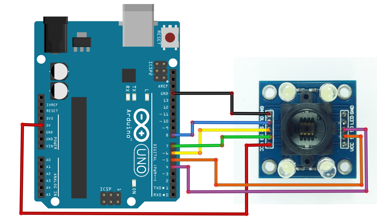
| Color Sensor Module | Arduino Uno |
| VCC | 5V |
| GND | GND |
| OUT | DIGITAL 8 |
| S3 | DIGITAL 7 |
| S2 | DIGITAL 6 |
| S1 | DIGITAL 5 |
| S0 | DIGITAL 4 |
ARDUINO CODE
Open Arduino IDE. Set the board to Arduino/Genuino Uno. Copy the code below to the programmer:
// TCS230 or TCS3200 pins wiring to Arduino
#define S0 4
#define S1 5
#define S2 6
#define S3 7
#define sensorOut 8

// Stores frequency read by the photodiodes
int redFrequency = 0;
int greenFrequency = 0;
int blueFrequency = 0;

void setup() {
  // Setting the outputs
  pinMode(S0, OUTPUT);
  pinMode(S1, OUTPUT);
  pinMode(S2, OUTPUT);
  pinMode(S3, OUTPUT);

  // Setting the sensorOut as an input
  pinMode(sensorOut, INPUT);

  // Setting frequency scaling to 20%
  digitalWrite(S0,HIGH);
  digitalWrite(S1,LOW);

   // Begins serial communication
  Serial.begin(9600);
}
void loop() {
  // Setting RED (R) filtered photodiodes to be read
  digitalWrite(S2,LOW);
  digitalWrite(S3,LOW);

  // Reading the output frequency
  redFrequency = pulseIn(sensorOut, LOW);

   // Printing the RED (R) value
  Serial.print("R = ");
  Serial.print(redFrequency);
  delay(100);

  // Setting GREEN (G) filtered photodiodes to be read
  digitalWrite(S2,HIGH);
  digitalWrite(S3,HIGH);

  // Reading the output frequency
  greenFrequency = pulseIn(sensorOut, LOW);

  // Printing the GREEN (G) value
  Serial.print(" G = ");
  Serial.print(greenFrequency);
  delay(100);

  // Setting BLUE (B) filtered photodiodes to be read
  digitalWrite(S2,LOW);
  digitalWrite(S3,HIGH);

  // Reading the output frequency
  blueFrequency = pulseIn(sensorOut, LOW);

  // Printing the BLUE (B) value
  Serial.print(" B = ");
  Serial.println(blueFrequency);
  delay(100);
}
Upload the code. Open Serial Monitor, and set baud rate to “9600, BOTH NL & CR”. It should display an output similar to below:

Place a red object in front of the sensor module. Take the values when the sensor is near the color and far from the color. Different ambient lightings give different output, so be sure that your ambient lighting is fixed.
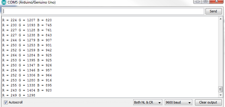
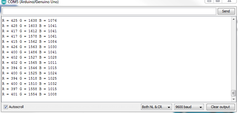
Measurements of red when near (left) and far (right)
Copy the red values. Do the same for blue and green objects.
Color Sensing
In Arduino IDE, copy the code below:
// TCS230 or TCS3200 pins wiring to Arduino
#define S0 4
#define S1 5
#define S2 6
#define S3 7
#define sensorOut 8

// Stores frequency read by the photodiodes
int redFrequency = 0;
int greenFrequency = 0;
int blueFrequency = 0;

// Stores the red. green and blue colors
int redColor = 0;
int greenColor = 0;
int blueColor = 0;

void setup() {
  // Setting the outputs
  pinMode(S0, OUTPUT);
  pinMode(S1, OUTPUT);
  pinMode(S2, OUTPUT);
  pinMode(S3, OUTPUT);

  // Setting the sensorOut as an input
  pinMode(sensorOut, INPUT);

  // Setting frequency scaling to 20%
  digitalWrite(S0,HIGH);
  digitalWrite(S1,LOW);

  // Begins serial communication
  Serial.begin(9600);
}

void loop() {
  // Setting RED (R) filtered photodiodes to be read
  digitalWrite(S2,LOW);
  digitalWrite(S3,LOW);

  // Reading the output frequency
  redFrequency = pulseIn(sensorOut, LOW);
  // Remaping the value of the RED (R) frequency from 0 to 255
  // You must replace with your own values. Here's an example:
  // redColor = map(redFrequency, 70, 120, 255,0);
  redColor = map(redFrequency, 220, 426, 255,0);

  // Printing the RED (R) value
  Serial.print("R = ");
  Serial.print(redColor);
  delay(100);

  // Setting GREEN (G) filtered photodiodes to be read
  digitalWrite(S2,HIGH);
  digitalWrite(S3,HIGH);

  // Reading the output frequency
  greenFrequency = pulseIn(sensorOut, LOW);
  // Remaping the value of the GREEN (G) frequency from 0 to 255
  // You must replace with your own values. Here's an example:
  // greenColor = map(greenFrequency, 100, 199, 255, 0);
  greenColor = map(greenFrequency, 246, 600, 255, 0);

  // Printing the GREEN (G) value
  Serial.print(" G = ");
  Serial.print(greenColor);
  delay(100);

  // Setting BLUE (B) filtered photodiodes to be read
  digitalWrite(S2,LOW);
  digitalWrite(S3,HIGH);

  // Reading the output frequency
  blueFrequency = pulseIn(sensorOut, LOW);
  // Remaping the value of the BLUE (B) frequency from 0 to 255
  // You must replace with your own values. Here's an example:
  // blueColor = map(blueFrequency, 38, 84, 255, 0);
  blueColor = map(blueFrequency, 150, 250, 255, 0);

  // Printing the BLUE (B) value
  Serial.print(" B = ");
  Serial.print(blueColor);
  delay(100);

  // Checks the current detected color and prints
  // a message in the serial monitor
  if(redColor > greenColor && redColor > blueColor){
      Serial.println(" - RED detected!");
  }
  if(greenColor > redColor && greenColor > blueColor){
    Serial.println(" - GREEN detected!");
  }
  if(blueColor > redColor && blueColor > greenColor){
    Serial.println(" - BLUE detected!");
  }
}
Upload the code. Open Serial Monitor, and set baud rate to “9600, BOTH NL & CR”.
OUTPUT
When placing a red object in front of the sensor, the serial monitor displays an output indicating that red color is detected. If a green colored object is placed, the serial monitor displayed a “GREEN detected” message, whereas a “BLUE detected” message is prompted if a blue object is placed in front of the sensor.
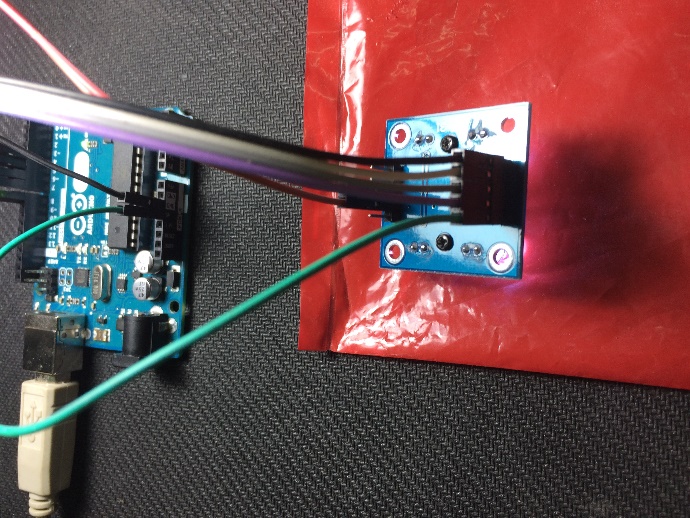
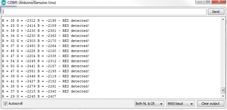
Setup for detecting red color (left) and its output in serial monitor (right)
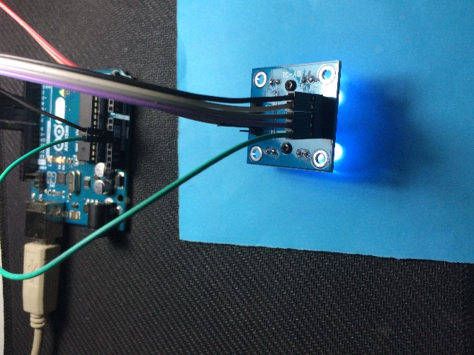
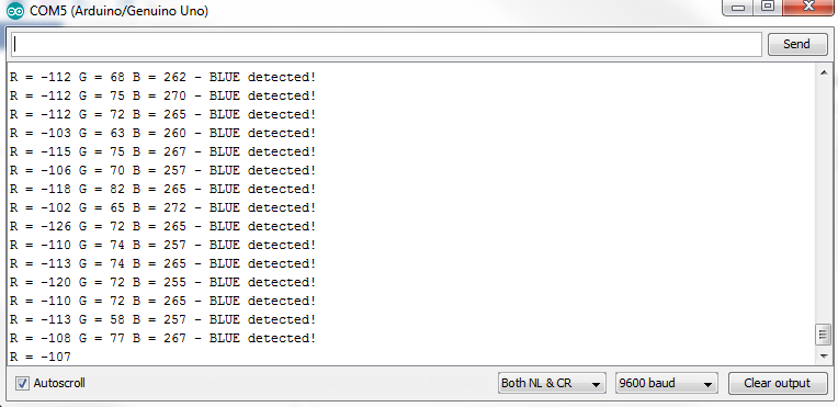
Setup for detecting blue color (left) and its output in serial monitor (right)
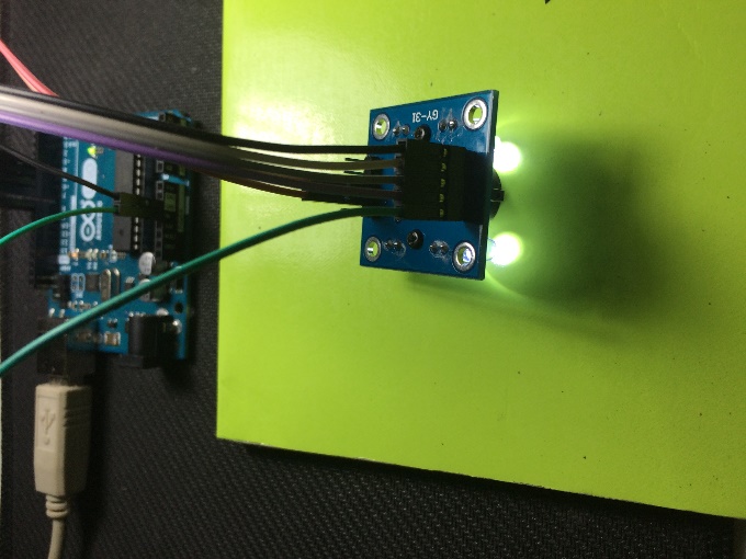
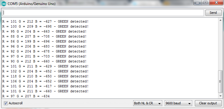
Setup for detecting green color (left) and its output in serial monitor (right)
References and other Applications
You can find more information, examples and resources below.
Arduino Color Detection by GPL3+
https://www.mouser.com/catalog/specsheets/TCS3200-E11.pdf
https://howtomechatronics.com/tutorials/arduino/arduino-color-sensing-tutorial-tcs230-tcs3200-color-sensor/