
ADXL335 Accelerometer Quickstart Guide
Get the PDF version of this guide here!
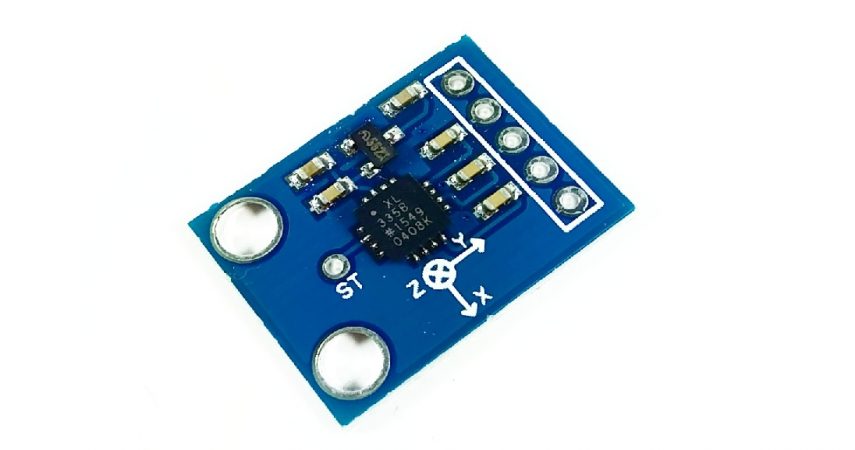
The ADXL335 Accelerometer Sensor is a 3-axis accelerometer that detects the tilt of the board and outputs the signal in analog voltages instead of serial communication. It means that you do not need to use complex code to determine the tilt of your board, instead you can make use of your Analog Pins for Arduino Uno!
HARDWARE SPECIFICATIONS
- 3-axis sensing
- Low power required (350 µA typical)
- With built-in voltage regulator for 5V pins
- Excellent temperature stability
PARTS LIST
For this quickstart guide, we will need the following materials:
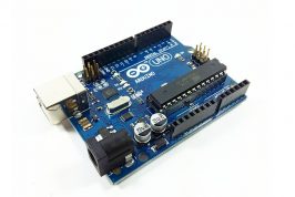
- 1 – Arduino Uno
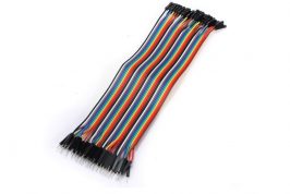
- Connecting wires
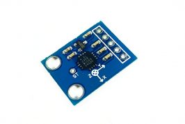
- 1 – ADXL335 3-axis accelerometer module
HARDWARE OVERVIEW
The 1 channel relay have 3 pins to be connected to the microcontroller: VCC, GND and IN. For the system to be controlled, the pins NO, COM and NC are used.
The table below describes the function of each pin in the module
| INPUT | Description | |
| GND | To be connected to the GND pin in a microcontroller. | |
| VCC | Supplies power to the module. Could be connected to a +5V pin or +3.3V pin. | |
| OUTPUT | ||
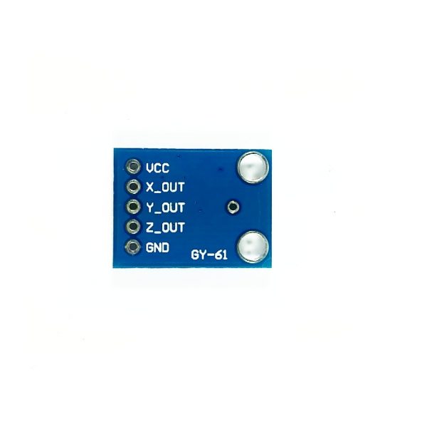
| X_OUT | Gives analog values in 0-1023 value for the x-axis | |
| Y_OUT | Gives analog values in 0-1023 value for the y-axis | |
| Z_OUT | Gives analog values in 0-1023 value for the z-axis | |
The orientation of the x,y and z-axis with respect to the module is printed below the ADXL335 module, with the z-axis pointing towards the top of the board.
WIRING CONNECTION
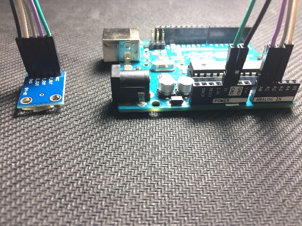
Setup the hardware as shown below:
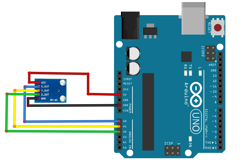
| Accelerometer Module (right to left) | Arduino Uno |
| VCC | 5V |
| X_OUT | Analog A0 |
| Y_OUT | Analog A1 |
| Z_OUT | Analog A2 |
| GND | GND |
ARDUINO CODE
Open Arduino IDE. Copy the code below into the programmer:
const int xpin = A0;                  // x-axis of the accelerometer
const int ypin = A1;                  // y-axis
const int zpin = A2;                  // z-axis (only on 3-axis models)
void setup() {
 // initialize the serial communications:
 Serial.begin(9600);
}

void loop() {
 // print the sensor values:
 Serial.print(analogRead(xpin));
 // print a tab between values:
 Serial.print("\t");
 Serial.print(analogRead(ypin));
 // print a tab between values:
 Serial.print("\t");
 Serial.print(analogRead(zpin));
 Serial.println();
 // delay before next reading:
 delay(100);
}
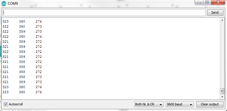
Upload the code into the Arduino Board. Open serial monitor. Set baud rate to “9600, Both NL & CR”.
OUTPUT
The output varies according to the position the sensor board is oriented. Rotating or moving the board changes the value for x, y, and z.
References and other Applications
You can find more information, examples and references below.
Netduino for Posture Correction by George Kartsonas
Lantern by Nord Projects