
Infrared Line Sensor Board (1 channel) Quickstart Guide
Get a PDF version of this file here!
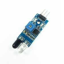
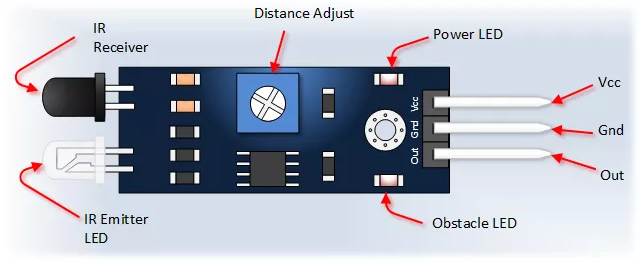
This Infrared Line or Obstacle Detection Sensor board is perfect for your line follower or obstacle detection robotic car projects. This is the 1 channel board version. When powered, you set detection level by adjusting the on board trimmer potentiometer. You can get the Output data in digital HIGH and LOW when line is detected in the OUT (digital output) pin.
It has an on board comparator circuit with adjustable potentiometer to set the reference/threshold voltage for the infrared detection level. It also has power and digital output LED indicator for easy debugging. The circuit is a pair of infrared emitter and phototransistor which send signal to each other when there is a white/clear surface and blocks any signal when there is black/dark surface.
In other applications, this sensor board can also be used for obstacle or wall detection projects.
HARDWARE SPECIFICATIONS
- Working Voltage: DC 3.3-5V
- Signal Output: 0 (detected), 1 (not detected)
- Detecting Distance: 2-30cm (adjustable)
- Detection Angle: degrees ~35
- Module Size: 32X14mm
- Use comparator LM393
- Board Size : 3.1CM * 1.5CM / 1.22 * 0.59″
- Dimension: Height: 7.3 mm, Width: 47.2 mm, Weight 2.1 g
PARTS LIST
For this quickstart guide, we will need the following materials. Click on the image for more information.
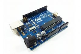
- Arduino Uno
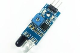
- Line Follower Sensor Board (1 channel)
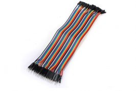
- Male – Female Connecting Wires
HARDWARE OVERVIEW
The line follower sensor has three pins: VCC, GND and Out.
| INPUT | Description | |
| GND | To be connected to the GND pin in a microcontroller. | |
| VCC | Supplies power to the module. Could be connected to a +5V pin or +3.3V pin. | |
| OUTPUT | ||
| Out | Sends a high or low pulse signal to indicate whether there is a black or a white color detected. | |
PREPARING THE ARDUINO IDE
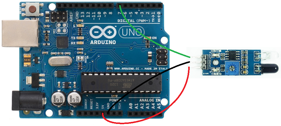
Connect the line sensor to the Arduino Board according to the table below:
Line/Obstacle Sensor —> Arduino
VCC —> 5V
GND —> GND
OUT —> DIGITAL PIN #7

ARDUINO CODE
This example will use the board as obstacle detection device.
This Line Sensor board can detect a black line in a white surface. This can be used for line follower robot projects. This same board can also be used for obstacle detection where you can detect a certain object or wall and do something after you detect the wall (example light and LED, sound a buzzer, or run an Arduino robotic car in different direction if you are building a robot).
For the following example code the use of the device is to detect a wall/obstacle and display a text alert.
Copy the code below and paste it in your Arduino IDE. Compile and Upload the code to your Arduino board.
// IR Obstacle Collision Detection Module
// Henry's Bench
// Rewritten Example by BITSTOC

int LED = 13; // Use the onboard Uno LED
int isObstaclePin = 7;  // This is our input pin
int isObstacle = HIGH;  // HIGH MEANS NO OBSTACLE

void setup() {
pinMode(LED, OUTPUT);
pinMode(isObstaclePin, INPUT);
Serial.begin(9600);
}

void loop() {
isObstacle = digitalRead(isObstaclePin);
if (isObstacle == LOW)
{
Serial.println("OBSTACLE Detected!!, OBSTACLE Detected!!");
digitalWrite(LED, HIGH);
}
else
{
Serial.println("clear");
digitalWrite(LED, LOW);
}
delay(200);
}
OUTPUT
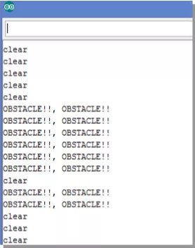
After uploading the code open your Arduino Serial Terminal and set the Baud to 9600. It will display if it is clear or an obstacle is detected.
Now place your hand or object in front of sensor and it will display an “Obstacle Detected” message on the Serial Terminal. The LED on the sensor board and the LED on the Arduino board connected to PIN13 will also light up. When no obstacle detected it will display a “clear” message.
If you have your hand or the object to detect in front of the sensor you may need to adjust the detecting capability. The trimmer potentiometer (blue box with screw terminal figure) on the sensor board is the one you set for the detection level. Try turning slowly the potentiometer from left to right until you have a detection and no detection output on the Serial Terminal.
The result may look like below.
References and Other Applications
http://www.playembedded.org/blog/en/2016/01/08/detecting-obstacle-with-ir-sensor-and-arduino/
http://henrysbench.capnfatz.com/henrys-bench/arduino-sensors-and-input/arduino-ir-obstacle-sensor-tutorial-and-manual/